Electric Guitar Audio Visualizer
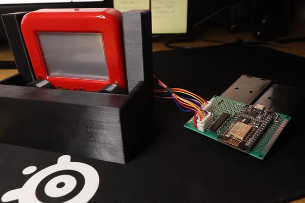
The idea was to make an "On the Go" light show for indie musicians. It had to be light, portable, customizable, and affordable. Simply just plug your guitar into it and BAM, instant light show.
The device in action
Technical Run Down
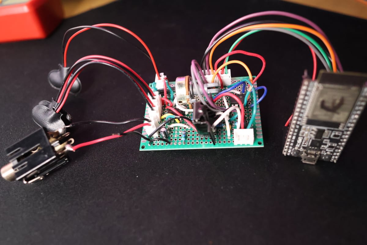
Essentially all this is, is a spectrum analyzer. The device samples the analog signal coming from the guitar and then it is transferred to a micro-controller where some magical DSP stuff happens and out come the pretty lights. Easy, right?
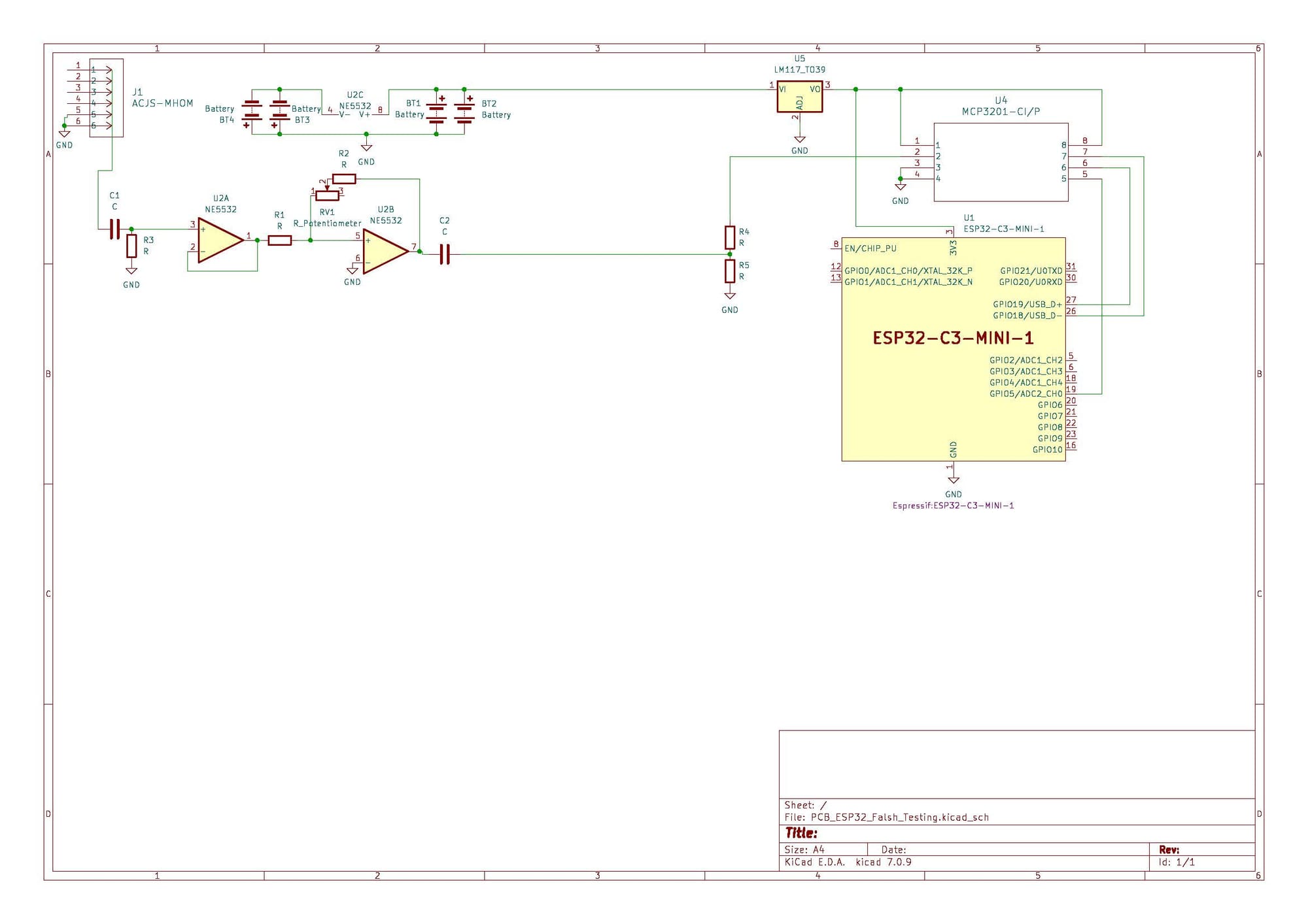
Here is the schematic to the design if you want to make something similar. There are some obvious improvements that I would suggest but over all it's a great project and it works well.
How it works
First the input. The thing on the top left corner of the schematic. An audio jack. That is where the input signal from the guitar comes from. Then there are two op-amps. One of them is a buffer stage and the other one is a gain stage. Then there is a voltage shifter that shifts the signal from the guitar up by half of the VDD voltage. That signal is then input to the signal line of an ADC.
The ADC is then connected to a microcontroller. It interfaces with the microcontroller with I2C protocol. After some sampling the microcontroller runs a Fourier transform using the signals that were transferred. This returns two arrays, one that contains frequency and one that contains magnitude.
So now all that needs to happen is for the magnitude and frequencies to be mapped to an LED strip. Which is pretty simple since each LED can be made to represent an individual frequency bin. The brightness of the LED can be adjusted by the magnitude and the color can represent a specific frequency.
Obviously everything needs power so for that there are four 9V batteries to power the entire circuit. Two sets of parallel connected batteries. One set is a negative polarity and the other is a positive one (so that can be a negative and positive voltage to the op-amps). There is also a 3V regulator since the digital components are powered by 3V.
That's pretty much it and it works. But let me tell you something: it has its faults. There are a few things I would change if I decided to bring this to production (such as ways to make it cheaper and more efficient).
What is wrong with it?
Firstly, there does not need to be two op-amps. The idea behind the two op-amps was to have a buffer stage and then an amplification stage. However this can just be a single stage.
Secondly, there is no reason there should be a voltage shifter. In my mind, I was thinking that this would mess up the DFT processing if the signal was not at the center of the dynamic rage when there was a 0V input, but if this in fact were a problem, then the values could just simply be shifted up inside of the microcontroller, through software, after they have been sampled. Saving some components and some PCB space.
The most obvious error, in my opinion, was the type of battery that was used. Instead of using a 9V battery and down regulating it to 3V, I should have used something closer to 3V and reduced the amount of power loss in down regulation.
Conclusion
Honestly this project was super fun to make and it took way longer than it should have. It has many issues but in the end, what really matters is that it works!
