Automated Plant Maintenance System
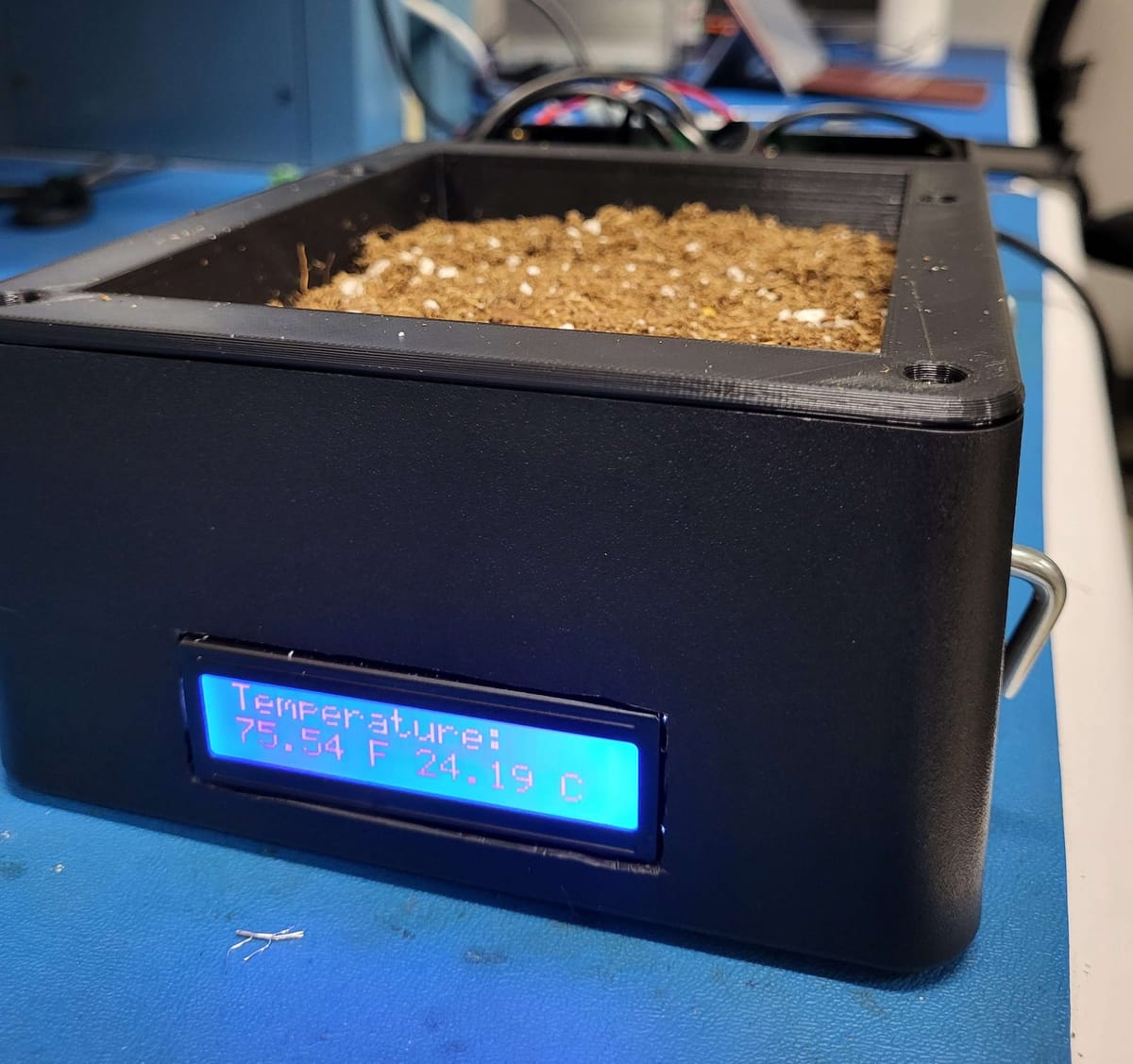
Pretty much, what this box does is maintain perfect soil and lighting conditions for a plant to grow. It comes with an app that allows the user to pick a soil temperature and soil humidity that best suits a specific plant. The box then maintains those conditions allowing the plant to grow under ideal conditions. This is all controlled by a phone which is connected to the box through Wi-Fi.
Technical Overview
This system functions on four main sub systems. The first two are the temperature and the moisture regulation systems. Each system consists of a way to measure and then adjust the temperature and moisture respectively. There are two smaller subsystems. The lighting system and the interfacing system. The lighting system is an adjustable LED light and the interface system consists of an LED screen and an android app.

Soil Moisture System
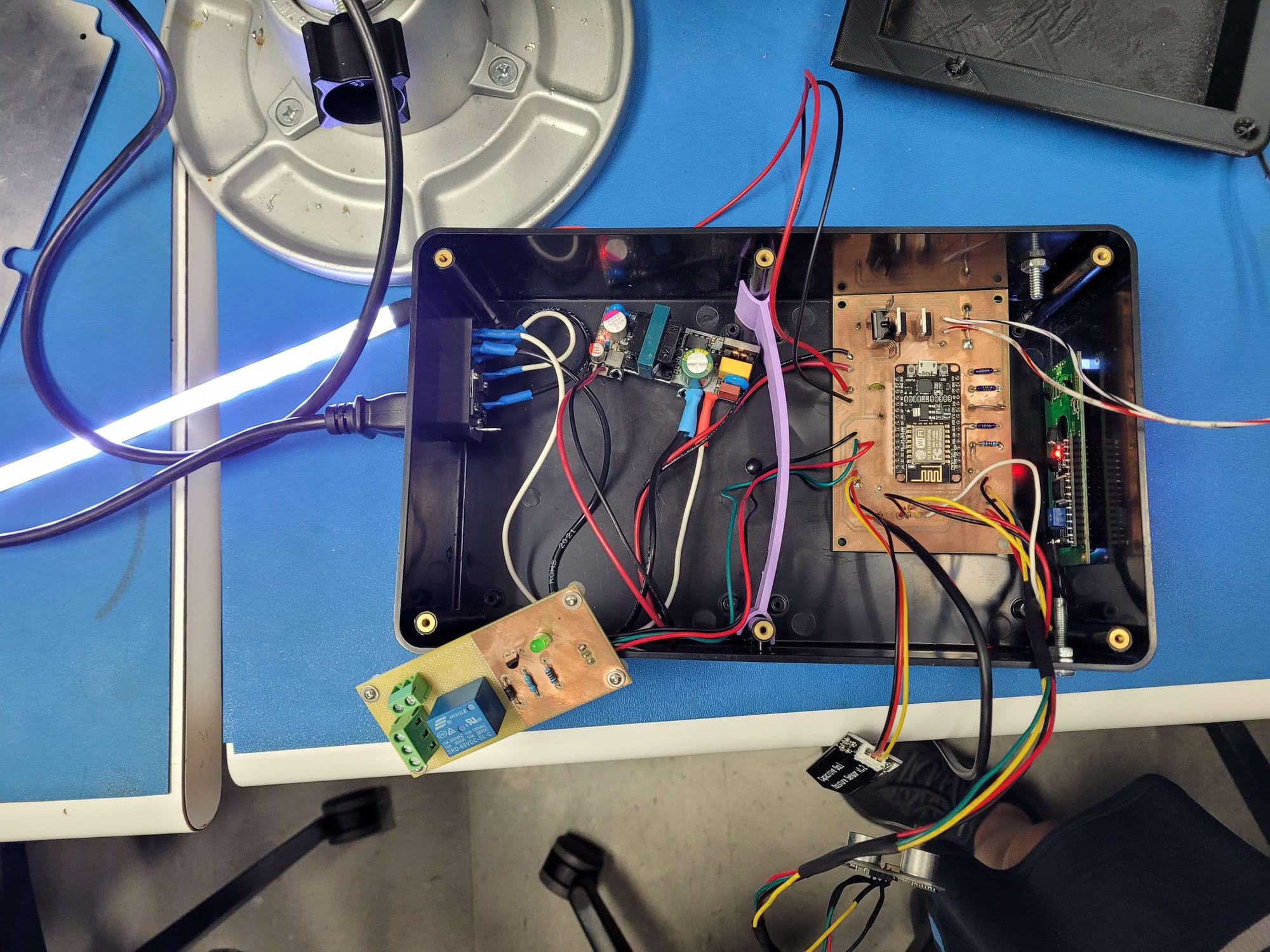
This sub system consisted of two main components, a capacitive moisture sensor and a water pump. First the user selects the desired moisture level (this is done through the app). The moisture sensor takes a reading of the soil ever few seconds. If the soil moisture reading from the sensor is lower than the desired level, the microcontroller triggers a small pulse through a GPIO pin to the gate of a MOSFET. This MOSFET acts as a switch that turns on and off a water pump. After a short burst of water, the system lets the water settle and the cycle repeats.
Soil Heating System
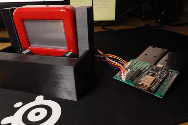
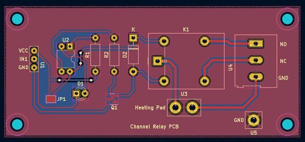
The main components for this sub system are a thermometer and a heating pad. Just like the moisture, the temperature can be set through the app. Once the temperature is set, the system begins to sense the temperature. If the temperature is too low then the microcontroller sends a short pulse, longer then the water pulse, through a GPIO pin to a relay. This relay works as a switch that turns on and off the heating pad. Something to note about the relay circuit is that it is separate from the other part of the circuit since this part of the circuit is 120V AC. That is why there are two separate PCBs in the picture of the system.
Lighting System
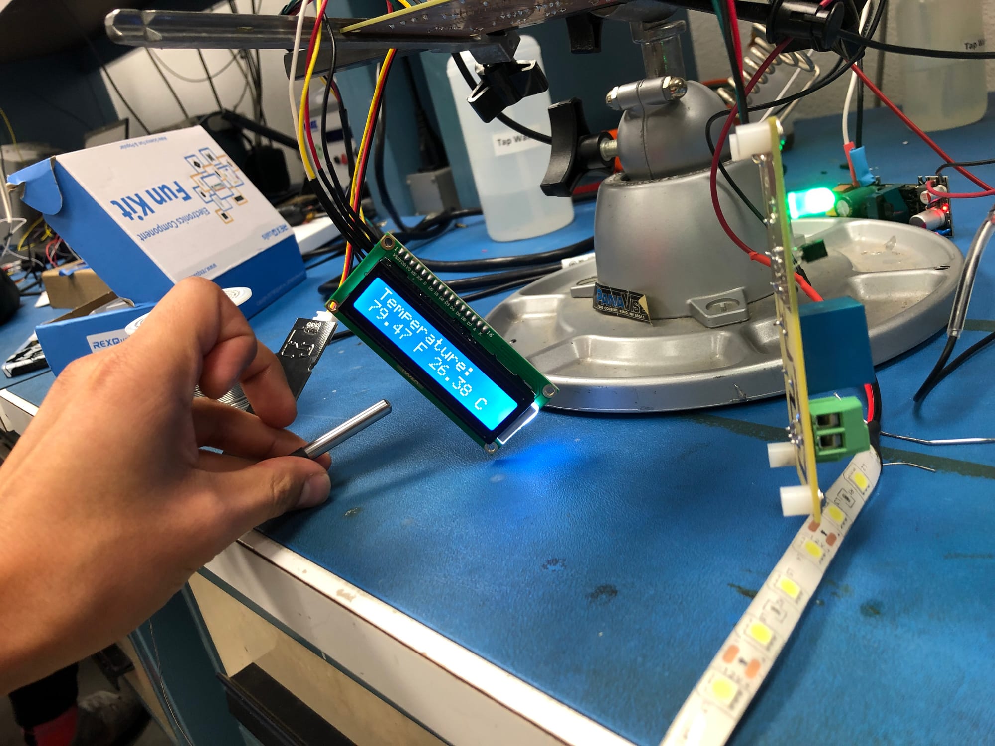
This lighting system is not a closed loop like the heating and moisture system. The lighting system is an open loop system. By this, I mean that the light level can be set by simply going to the app and selecting the desired light level. That's pretty much it. The interesting thing about the lighting system circuit, is that it has a MOSFET acting as a switch. The then microcontroller uses a PWM signal to quickly switch the MOSFET and, depending on the duty cycle of the PWM signal, the brightness of the LED strip is adjusted.
Interface
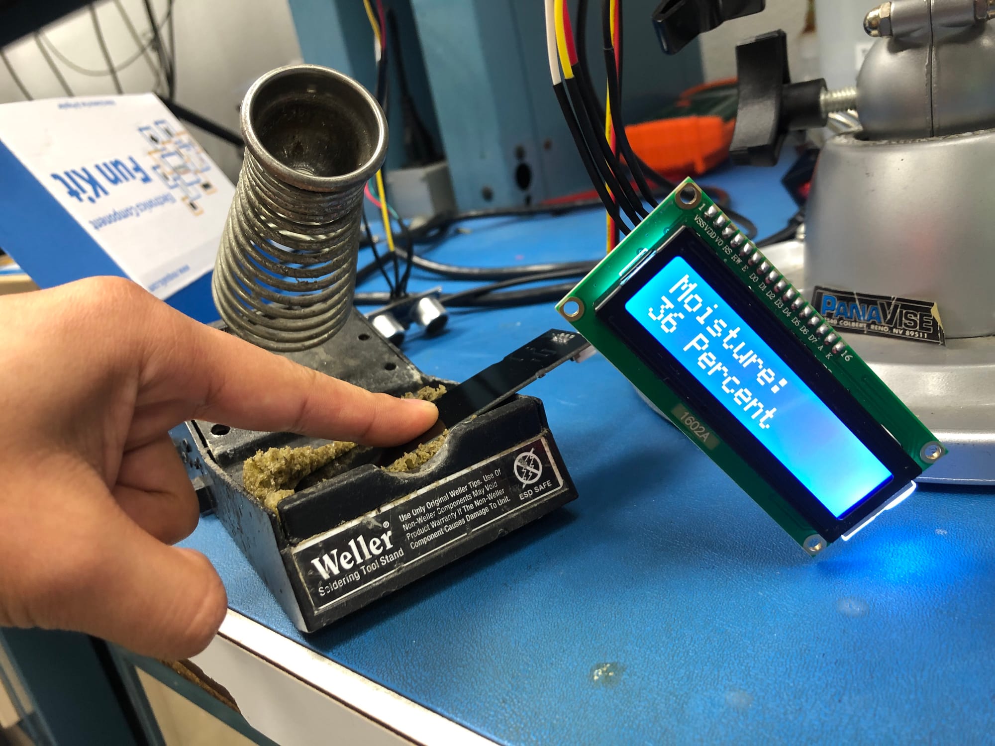
There are two ways to interface with the system. One is through an app and the other is through a built-in LED screen. The LED screen alternates between displaying temperature and moisture level in a never ending cycle. The interesting part comes from the app. The microcontroller has a built-in Wi-Fi card which means that a phone can be connected to it. We built a custom Android app that enables the user to interface with the system. Through this app the temperature, moisture, and light levels can be set.

PCB
The PCBs were pretty simple. The one thing I do want to mention though is that there were two separate ones for this project. The reason for this is that the heating pad used 120V AC to operate and everything else is low voltage. So in order to protect the low power devices from being damaged from the 120V lines, two separate boards were made. One that has a relay and one that holds every thing else.

Conclusion
This project was part of my senior design project. It was super cool too see an idea come to life. This was the first time I worked on anything PCB related. I also got to work on a team with 3 other engineers. We had issues that we eventually resolved but overall this was a great experience. This goes on my list for top 3 projects that I have worked on.
