Self Drawing Etch A Sketch
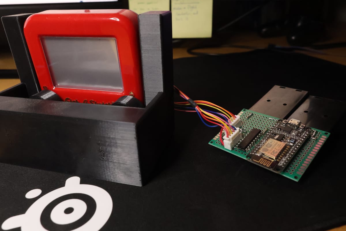
This is literally the most useful thing I have ever made. It makes my life so much simpler and I've saved hundreds of hours because of this. It's an automatic Etch A Sketch machine. So essentially I can use my PC to make a drawing and then it magically appears on my Etch A Sketch. So instead of having to turn some inconvenient knobs, I can just use a computer mouse to make the drawing instead. Such a time saver!
Technical Overview
In my opinion, this is one of the more technically interesting things that I've made. It combines Python, IoT Clouds, C programming, APIs, 3D modeling and analog circuits all into one bag of useless nonsense to create something that is borderline magical. So here is the gist. Pretty much I made a super stripped down version of MS paint using Python. When the user draws something on this GUI, the coordinates of the drawing are transferred over Wi-Fi to a microcontroller via Arduino's IoT cloud services. That microcontroller then translates the coordinates into GPIO activations which control some stepper motors. Those stepper motors are connected to the Etch A Sketch knobs and so they turn the knobs in accordance to the coordinates of the drawing. Then if you wait a few seconds voilà! A drawing on the Etch A Sketch.
How it works
Explaining this in just words seems fairly inefficient, so I made a block diagram to summarize what is going on.
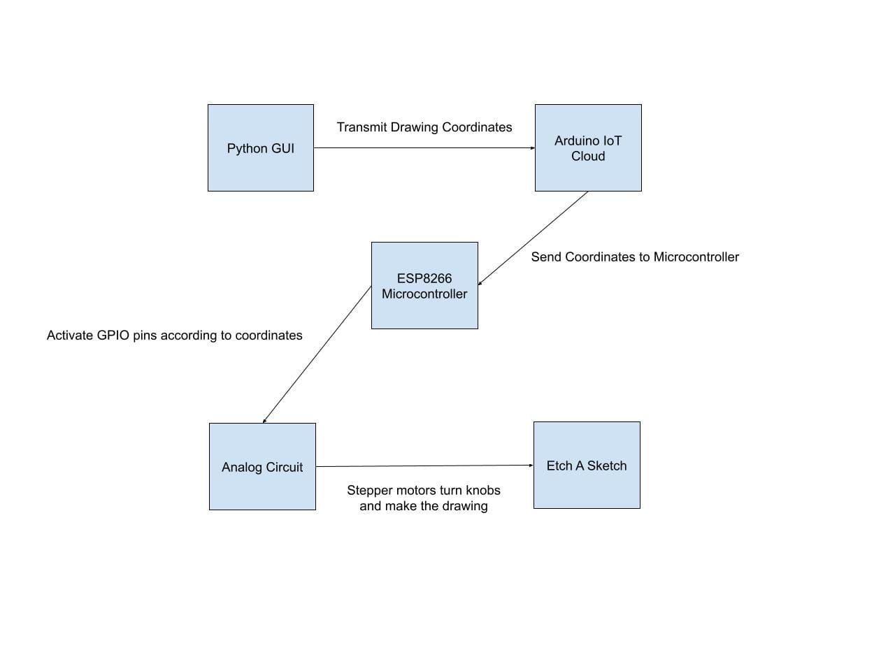
Now let me break this down.
Python GUI
Like I mentioned earlier, I made a stripped down version of MS paint in Python using Python's tkinter library. This program saves the coordinates of the drawing into two ordered lists. One list contains the X coordinates and the other list contains the Y coordinates of the drawing. Below is a video of this process in action.
Arduino's IoT Cloud
Once the two lists are created, they need to be transmitted to the microcontroller for processing. To do this, I wrote some Python code to do this data transfer through Arduino's IoT Cloud, which I interfaced with through an API. The code transmits the data to the cloud using Arduino's IoT Cloud "Messenger Widget" which is just a way to send and receive strings. Once the data is sent to the cloud, the data is then transmitted from the cloud to the microcontroller and then saved as a string variable internally on the device and can be translated into stepper motor controls. You can see that there are two messenger widget windows. That is because one widget stores the X coordinates and the other stores the Y coordinates.

Another thing to note is that, the widget windows only have a subset of the entire list of numbers. Ideally, the Python script would transmit all the coordinates from the Python script to the microcontroller all at once, but that is not possible due to the microcontroller's limited memory. So in order to get around this, I wrote the Python script such that it only sends around 30 or so items at a time. The hardware then processes the coordinates and then signals the Python script to send some more coordinates. The process is repeated over and over until the entire drawing has been made.
Microcontroller Circuit
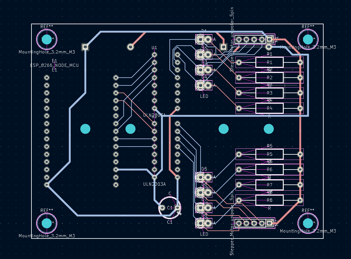
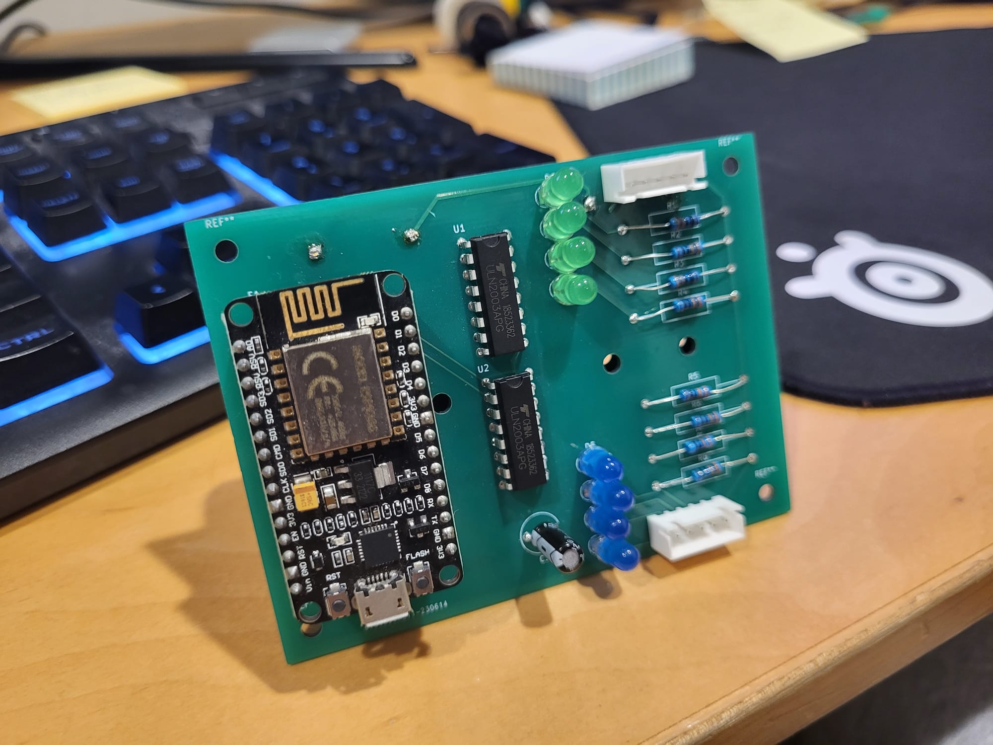
This is what the circuit looks like.

It's a super simple circuit. It is a microcontroller, connected to a motor driver IC, connected to 2 stepper motors, and some LEDs. The motor driver is essentially just an IC with a bunch of transistors that act as switches which are toggled by the GPIO pins of the microcontroller. Instead of using as many GPIO pins as I did, I could have used some sort of MUX, but I had plenty of pins to go around so I just went ahead and did it this way instead.
PCB
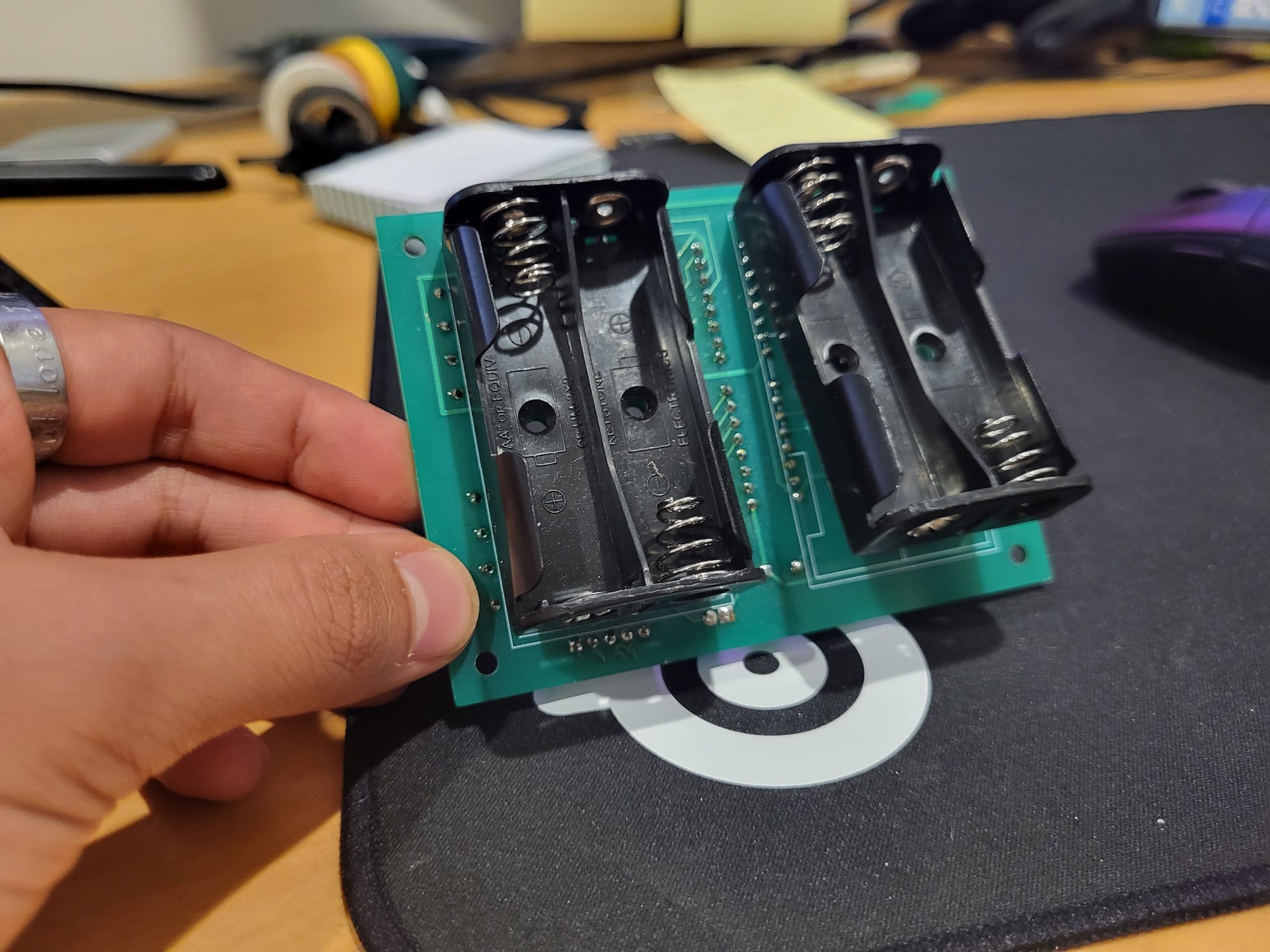
The PCB was a simple two layer PCB designed in KI Cad. The most challenging part about this was figuring out how to fit the battery holder such that it wouldn't obscure the other components while still maintaining a slim form factor.
3D modeling
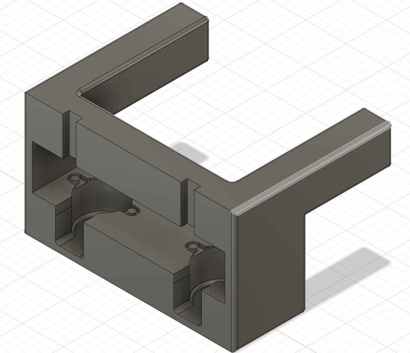
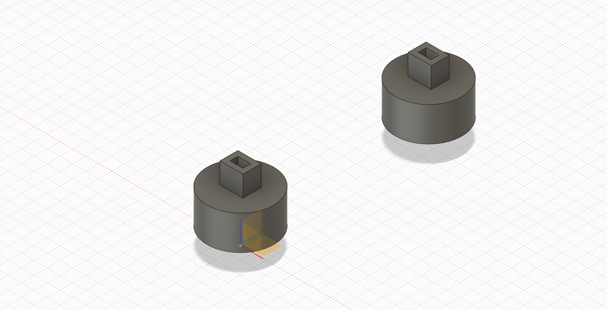
Honestly, this was probably the hardest and most time consuming part of the project for me. I am an electrical engineer and that is where I am comfortable. Making a model to mount the stepper motors and the Etch a Sketch on to, took me about 10 iterations to get right. And the thing about physical models is, the feed back loop can be quite slow since 3D printing things takes time. But non-the less here is what I managed to make.
Conclusion
This project was so much fun. If I were to do it differently and if I decided to make a more refined version than the one that I made, I would make a nicer PCB, ask a mechanical engineer to help me on the physical design, and use a more power full processor that has more memory. Over all this is one of my favorite projects since it combines so much into one silly little thing and it brings a smile to my face every time I see it do its thing.
